The trivial option (usually not recommended): Just draw a line between two boxes to indicate that a dependency exists.
If you need more serious options, you have at least the following options (orderd by required effort for creating and maintaining such descriptions):
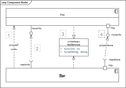
- Give the line a label (to make it referencable) and explain its meaning in a table below the diagram. This should be sufficient for many non-safety-critical systems.
- Use the provided/required notation (aka “ball/socket”), explicitely denoting which services/data/events the providing building block offers. There’s a nice explanation by Martin Fowler on this option.
- Use distinct interface building blocks.
- Use ball-and-socket notation in combination with port symbols.
The following diagram shows all these options.